
Introduction
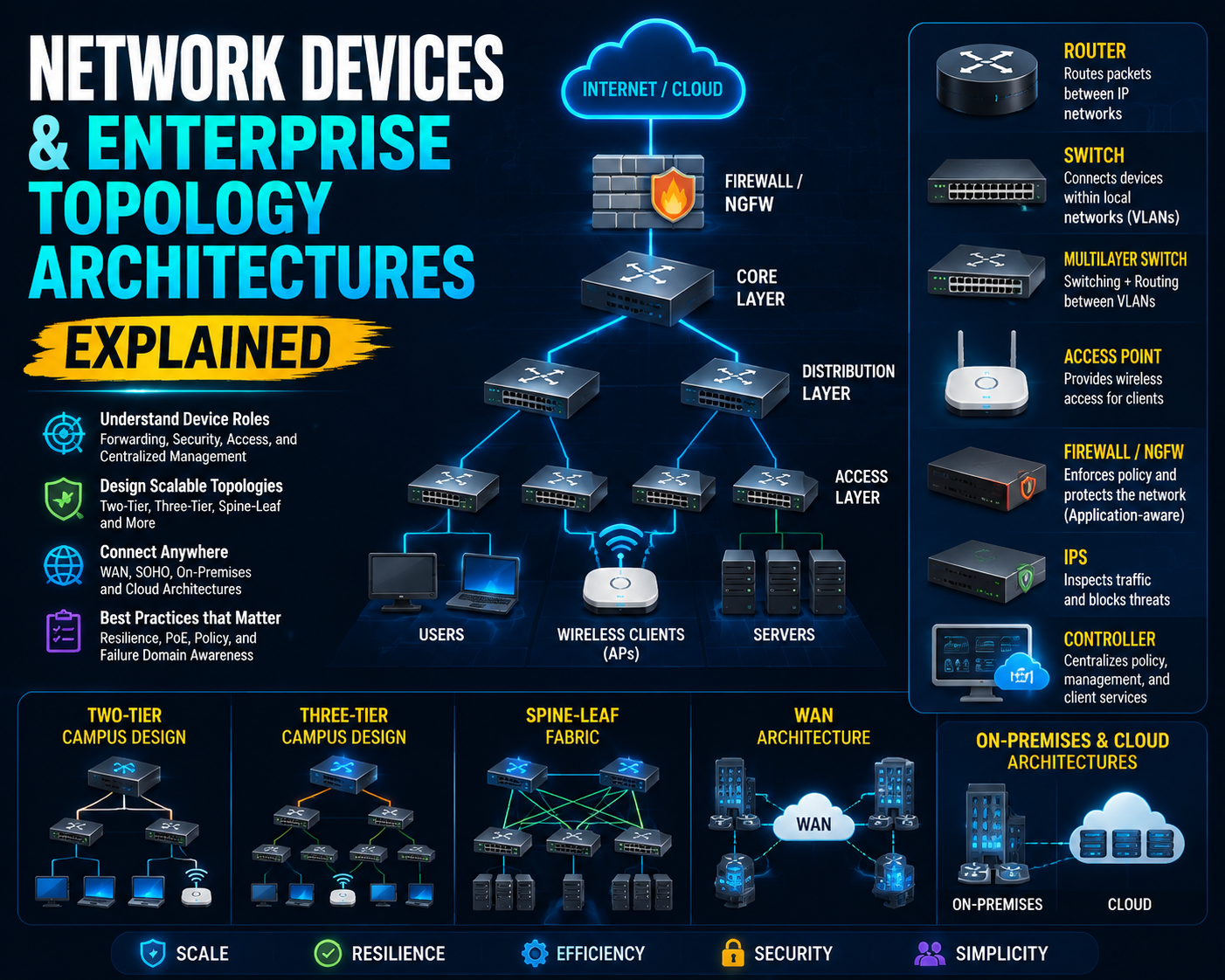
Network architecture becomes easier to reason about when every component has a clear responsibility. A router selects Layer 3 paths, a switch connects local segments, an access point bridges wireless clients into a wired network, and a controller centralizes policy or management. Enterprise topologies arrange these roles to balance scale, resilience, cost, and operational simplicity.
Architecture Overview
Traffic normally moves through an access layer near endpoints, an aggregation or distribution function that applies policy and summarizes connectivity, and a core or fabric that provides fast transport. A small deployment can collapse several functions into one device. A larger design separates them to reduce failure domains and improve scale.
Core Components
Forwarding, Security, and Access Roles
Routers forward packets between IP networks. Layer 2 switches forward Ethernet frames within VLANs, while multilayer switches can also route between them. Next-generation firewalls enforce application-aware policy, and intrusion prevention systems inspect traffic for malicious patterns. These controls do not replace correct addressing or routing; they add policy to a working path.
Access points provide radio access, and Wireless LAN Controllers (WLCs) coordinate configuration, policy, and client services in controller-based designs. Endpoints originate or consume traffic, while servers provide shared applications and infrastructure services. Controllers may also manage wired, wireless, or cloud-managed estates through centralized interfaces.
Power over Ethernet (PoE) allows compatible switches to deliver data and electrical power over supported copper Ethernet cabling. A device must fit both the switch's per-port capabilities and its total power budget. An interface can carry data correctly yet fail to power an access point or phone when the budget or negotiation is insufficient.
How Topologies Organize Components
A two-tier campus commonly combines core and distribution functions and connects them to access switches. A three-tier design separates access, distribution, and core layers, which can improve modularity in larger environments. A spine-leaf fabric connects each leaf to each spine, providing predictable equal-cost paths for east-west data-center traffic.
Wide-area networks (WANs) join geographically separated sites across provider or Internet services. A small-office/home-office design usually favors fewer devices and simpler redundancy. On-premises and cloud environments differ in ownership and control surfaces, but both still require address plans, routes, policy boundaries, and observable dependencies.
Design Considerations
Choose an architecture by traffic pattern, failure-domain requirements, scale, operational skill, and budget. Do not choose a three-tier or spine-leaf design merely because it is more elaborate. Document where Layer 2 ends, where Layer 3 begins, where policy is enforced, how management access works, and which components depend on shared power or control systems.
Best Practices
- Draw logical and physical paths separately.
- Identify single points of failure and shared dependencies.
- Size PoE from documented device requirements and switch budgets.
- Keep management, control, and data-plane roles distinct.
- Validate cloud or controller reachability before attributing a failure to forwarding hardware.
Common Mistakes
Common mistakes include calling every switch a router, assuming a firewall creates missing routes, overlooking an uplink shared by multiple access devices, and treating a logical controller as if it were always in the data path. Another frequent error is copying a topology without confirming that its traffic pattern matches the intended workload.
Certification Relevance
CCNA v1.1 expects learners to explain device roles and compare two-tier, three-tier, spine-leaf, WAN, small-office/home-office, on-premises, and cloud architectures. Focus on ownership and trade-offs: which component forwards, which applies policy, which centralizes management, and which failure affects the observed path.
Conclusion
A useful architecture diagram is a dependency map. When device roles and topology boundaries are explicit, configuration and troubleshooting become systematic rather than command-driven guesswork.