
Introduction
Reliable network diagnosis begins with the physical link and follows data upward. Media carries signals, Ethernet delivers frames on a local segment, Internet Protocol delivers packets between networks, and transport protocols provide application-facing communication behavior. Each layer exposes different evidence and failure modes.
What the Data Path Contains
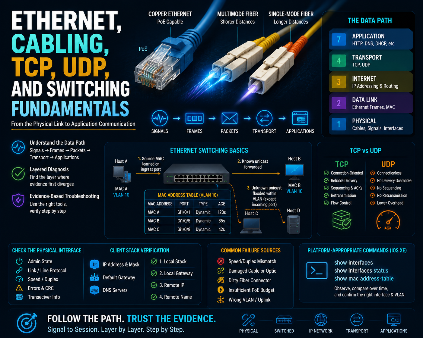
Copper Ethernet is common for endpoint access and can support Power over Ethernet. Multimode fiber is typically used for shorter optical links within buildings or data centers, while single-mode fiber supports longer distances. Actual reach and speed depend on the specific transceiver, cable category, wavelength, and platform documentation—not simply the words copper or fiber.
Ethernet can operate over shared-media concepts or point-to-point switched links. Modern switched Ethernet normally gives each port its own collision domain. A speed or duplex mismatch, damaged medium, unsuitable optic, or dirty fiber connection can still produce errors and unstable throughput.
Why Ethernet Evidence Matters
A switch learns a source Media Access Control (MAC) address on the ingress port and records it in its MAC address table for the associated VLAN. For a known destination, it forwards toward the recorded port. For an unknown unicast destination, it floods within the VLAN except back through the incoming port. Dynamic entries age out when no qualifying traffic refreshes them.
This behavior explains why an empty or incorrect MAC table points toward a local Layer 2 issue, while a correct local entry does not prove routing or application success.
Core Concepts
Diagnose the Physical Interface First
Check administrative state, line protocol, negotiated speed and duplex, error counters, and transceiver information supported by the platform. Rising cyclic redundancy check errors often suggest corrupted frames caused by media, optics, interference, or negotiation problems. Collisions on modern full-duplex switched links are abnormal and deserve investigation.
Compare TCP and UDP
Transmission Control Protocol (TCP) establishes a connection and provides sequencing, acknowledgments, retransmission, and flow control. User Datagram Protocol (UDP) sends independent datagrams without those delivery mechanisms. Neither protocol is universally better: an application chooses the behavior it needs. A successful ping does not prove that a TCP or UDP application port is reachable.
Verify the Client Stack
On Windows, macOS, or Linux, verify the address, prefix or mask, default gateway, and DNS servers before changing network infrastructure. Then test progressively: local stack, local gateway, remote IP address, and remote name. This separates addressing, routing, and name-resolution failures.
Practical Verification
On Cisco IOS XE, platform-appropriate forms of show interfaces, show interfaces status, and show mac address-table provide physical and switching evidence. Treat commands as observation tools: compare counters over time and confirm the relevant interface and VLAN rather than reading one snapshot in isolation.
Common Learning Challenges
- Assuming link-up means error-free transport
- Confusing MAC learning with destination learning
- Expecting a switch to learn addresses from frames it never receives
- Using ping as proof that an application works
- Blaming DNS before testing reachability by IP address
- Selecting media without checking transceiver and distance compatibility
Conclusion
Trace a failure from signal to frame to packet to transport session. The layer where evidence first diverges from the intended state usually identifies the component that owns the next diagnostic step.