
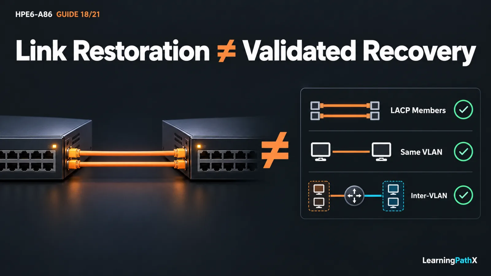
Validate a small campus switching lab by proving forwarding within a virtual local area network (VLAN), routed communication between VLANs and negotiated Link Aggregation Control Protocol (LACP) membership separately. Record that healthy baseline, disable one aggregation member, compare the remaining path with the prediction, restore the member and repeat every acceptance check. This procedure integrates Internet Protocol version 4 (IPv4) gateway reasoning with switch evidence; command completion alone is not acceptance.
The original scenario represents two rooms connected by a redundant uplink. It uses two standalone CX 6300 switches running AOS-CX 10.13 and three test hosts. It is an isolated hardware-lab design, not a reported execution or a claim about simulator fidelity. There is no production connection, external router, dynamic routing or stack construction.
Prerequisites and Recovery Boundaries
Complete HPE6-A86: Building and Validating LACP Link Aggregation, HPE6-A86: Implementing Inter-VLAN and Static Routing, and HPE6-A86: Troubleshooting Switched and Routed Connectivity first. You should already understand logical membership, gateway/return decisions and evidence-based fault isolation. This exercise applies those skills to one acceptance record rather than repeating their full tutorials.
Provide two eligible same-speed uplink ports per switch, supported media, three independently configured hosts and exclusive ownership of the lab. Confirm that example ports 1/1/47 and 1/1/48 exist on the actual models. Reserve an unused link aggregation group (LAG) 1 and VLANs 10, 20 and 99, with no conflicting configuration or traffic policies.
Retain authorized consoles on both switches. Preserve any established out-of-band management network separately; no management path may depend on the test uplink. Disconnect all lab data cables before preparation and exclude every additional inter-switch path. Keep startup configuration unchanged. From each switch's manager context, create and inspect that device's own baseline checkpoint:
switch# copy running-config checkpoint pre-campus
switch# show checkpoint pre-campus
Stop if either baseline or recovery login is unavailable. Record original host settings too; a switch checkpoint cannot restore a host. All gateway and forwarding interfaces below use the default virtual routing and forwarding (VRF) context.
Topology and Address Plan
Connect A 1/1/47 to B 1/1/47 and A 1/1/48 to B 1/1/48 only after preparation. Both links belong to one Layer 2 LAG. Its native VLAN is 99 and its explicit allowed set is 10, 20 and 99 at both ends. The data VLANs are tagged across the trunk; VLAN 99 has no test host or gateway.
| Host | Attachment | Address | Default gateway |
|---|---|---|---|
| Room-A client | A 1/1/1, access VLAN 10 | 192.0.2.10/24 | 192.0.2.1 |
| Room-B client | B 1/1/1, access VLAN 10 | 192.0.2.20/24 | 192.0.2.1 |
| Room-B service | B 1/1/2, access VLAN 20 | 198.51.100.20/24 | 198.51.100.1 |
Only A has switched virtual interfaces (SVIs): VLAN 10 at 192.0.2.1/24 and VLAN 20 at 198.51.100.1/24. These illustrative subnets are directly attached to A, so this lab needs neither a static route between them nor a default route. B switches the two VLANs; adding duplicate gateway addresses there would change the design.
Predict the paths before configuration. The two clients communicate within VLAN 10 across the LAG. Either client reaches the service through A's routing. Even the Room-B client must cross to A for that inter-VLAN decision and return through the trunk toward B's service port. Correct return gateways are therefore part of acceptance.
Prepare the Common Switching Configuration
Apply this block on both switches while all data cables remain disconnected. Both peers use active LACP, which is a supported negotiation combination:
switch# config
switch(config)# vlan 10,20,99
switch(config)# interface lag 1
switch(config-lag-if)# shutdown
switch(config-lag-if)# no routing
switch(config-lag-if)# vlan trunk native 99
switch(config-lag-if)# vlan trunk allowed 10,20,99
switch(config-lag-if)# lacp mode active
switch(config-lag-if)# exit
switch(config)# interface 1/1/47
switch(config-if)# lag 1
switch(config-if)# shutdown
switch(config-if)# exit
switch(config)# interface 1/1/48
switch(config-if)# lag 1
switch(config-if)# shutdown
switch(config-if)# exit
switch(config)# interface 1/1/1
switch(config-if)# no routing
switch(config-if)# vlan access 10
switch(config-if)# no shutdown
switch(config-if)# end
VLAN lists create the required VLANs without entering a single-VLAN context. Native-VLAN configuration can permit all VLANs, so the explicit allowed list immediately follows it. Forwarding configuration belongs on the logical LAG. Membership assignment removes nondefault member configuration; reassert shutdown after each assignment and verify actual state before cabling.
On B only, prepare the service attachment:
switch# config
switch(config)# interface 1/1/2
switch(config-if)# no routing
switch(config-if)# vlan access 20
switch(config-if)# no shutdown
switch(config-if)# end
On A only, configure the gateways after the VLANs exist:
switch# config
switch(config)# interface vlan 10
switch(config-if-vlan)# ip address 192.0.2.1/24
switch(config-if-vlan)# no shutdown
switch(config-if-vlan)# exit
switch(config)# interface vlan 20
switch(config-if-vlan)# ip address 198.51.100.1/24
switch(config-if-vlan)# no shutdown
switch(config-if-vlan)# end
Inspect both running configurations. Confirm the logical trunk, member assignments, shutdown states and unique gateways, then cable the two reserved uplinks and three host attachments. Configure each host from the address table and permit the selected test traffic through its firewall. Routing deliberately allows this lab's inter-VLAN exchange; it is not a complete security policy.
On both switches, enable the logical interface and its physical members:
switch# config
switch(config)# interface lag 1
switch(config-lag-if)# no shutdown
switch(config-lag-if)# exit
switch(config)# interface 1/1/47
switch(config-if)# no shutdown
switch(config-if)# exit
switch(config)# interface 1/1/48
switch(config-if)# no shutdown
switch(config-if)# end
Establish Observable Acceptance
Record timestamps, command context and actual results. On both switches, collect:
switch# show running-config
switch# show vlan
switch# show lacp aggregates lag1
switch# show lacp interfaces 1/1/47
switch# show lacp interfaces 1/1/48
switch# show mac-address-table dynamic vlan 10
Use the member-state legend to verify synchronization, collecting and distributing, and compare the partner identity with the intended peer. A configured member or illuminated link does not prove negotiated forwarding. Examine Media Access Control (MAC) learning after generating host traffic: remote VLAN 10 host learning should point toward the logical aggregation, while local learning points toward access ports.
On A, inspect show interface vlan 10, show interface vlan 20 and show ip route. Confirm both gateway interfaces are operational and both host prefixes have the intended connected routes. Check Address Resolution Protocol (ARP) evidence with show arp vrf default after host tests; a mapping is supporting evidence, not proof of application delivery.
Complete these tests with a small, fixed number of permitted host probes or an approved application exchange. Record actual loss and results; no successful output is asserted here.
| Test | Required observation | What it distinguishes |
|---|---|---|
| Every host to its gateway | Intended gateway responds | Local membership and gateway reachability |
| Room-A client to Room-B client, then reverse | Same-VLAN exchange works | VLAN 10 forwarding across the LAG |
| Each client to Room-B service, then reverse | Routed exchanges work | Both data VLANs, A's gateways and host return decisions |
| Separate management check | Authorized access remains available | Recovery path is independent of the experiment |
Do not begin the fault test until both members and all traffic checks pass. If baseline acceptance fails, follow the recorded failing exchange through membership, negotiated state, gateway, route and endpoint evidence. Fix a confirmed cause through the prerequisite troubleshooting workflow before continuing.
Introduce One Reversible Member Failure
Predict that removing one member reduces available aggregation capacity while leaving the other eligible path. A single flow is not guaranteed to use both members beforehand, so unchanged probe results do not prove doubled bandwidth or a hitless failover.
From A's retained console, disable only the reserved member 1/1/47:
switch# config
switch(config)# interface 1/1/47
switch(config-if)# shutdown
switch(config-if)# end
Repeat LACP observations at both ends. Verify the failed member leaves forwarding and 1/1/48 remains synchronized and eligible. Repeat the same host tests, recording any interruption and checking whether communication recovers over the surviving member. Do not inject a second fault. If the surviving path is unhealthy, stop and restore the disabled member rather than changing VLANs, routes and policies simultaneously.
Restore A 1/1/47 with no shutdown in its interface context. Recheck partner identity and both forwarding members, repeat the entire acceptance table, and verify management access. Recovery requires restored redundancy and service evidence, not merely the returning link light.
Cleanup and Record the Causal Result
For this temporary lab, disconnect all data cables first. Through each console, run checkpoint rollback pre-campus to restore that device's own baseline. Rollback replaces running configuration and can remove every intervening change, which is why exclusive ownership matters. Verify original interfaces, VLANs, routes and management access before reconnecting the original topology; restore host settings separately. Startup remains unchanged.
Keep a compact record of topology, healthy evidence, predicted failure, actual degraded observations, restoration and cleanup. A successful exercise explains why same-VLAN forwarding, routing and one-member resilience worked, or identifies precisely which expectation failed. That record is more useful than an unqualified claim that the network passed.
Authoritative Sources
- AOS-CX 10.13 Fundamentals Guide
- AOS-CX 10.13 Layer-2 Bridging Guide
- AOS-CX 10.13 Link Aggregation Guide
- AOS-CX 10.13 IP Routing Guide
- AOS-CX 10.13 IP Services Guide
- AOS-CX 10.13 Diagnostics and Supportability Guide