
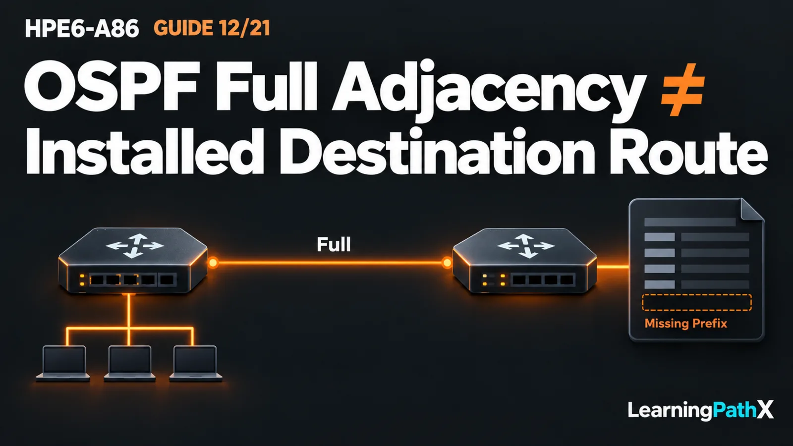
Open Shortest Path First version 2 (OSPFv2) exchanges link-state information for Internet Protocol version 4 (IPv4), builds a shared view of an area's topology and calculates paths from each router's perspective. Validate its results in stages: check the expected neighbor relationships, inspect the topology information and calculated routes, then confirm which routes the switch selects for forwarding. A healthy adjacency does not prove that a particular destination prefix is advertised or installed.
This explanation uses AOS-CX 10.13 on CX 6300 and one isolated area-0 example. It assumes working Layer 3 interfaces and host gateways, as established in HPE6-A86: Implementing Inter-VLAN and Static Routing. It explains an already configured design and its evidence rather than supplying a new configuration recipe. The official Switching Fundamentals course includes OSPF; that does not create a separately published exam percentage for this lesson.
Architecture Overview: Topology Before Routes
OSPF routers describe their links through link-state advertisements (LSAs). Routers in a converged area maintain consistent relevant information in their link-state databases (LSDBs). Each router then runs a shortest path first (SPF) calculation with itself as the starting point. Shared topology knowledge therefore does not mean that every router has the same next hop toward a destination.
Interface cost influences the calculated path. A lower total cost can make one path preferable within OSPF; it is not a measurement of available application throughput. Changes in links and advertisements can trigger recalculation, but convergence is a process with observable states, not an unconditional promise of uninterrupted traffic.
An area groups participating interfaces and topology information. Area 0, also written 0.0.0.0, is the backbone area. Using only area 0 keeps this example within one topology scope; multiarea design and redistribution are separate subjects. Verify the area on each intended participating interface, rather than assuming that creating a routing process enrolls every connected network automatically.
Router Identity, Context and Interface Participation
The router ID is a 32-bit identifier displayed in IPv4-address form. Give routers unique, stable identities and distinguish that identifier from a packet's forwarding next-hop address. In this example, A has router ID 1.1.1.1 and B has 2.2.2.2; those values identify the routers and are not the transit addresses used to reach the neighboring device.
AOS-CX associates routing processes and interfaces with virtual routing and forwarding (VRF) contexts. This example uses the default VRF. Inspect the correct process and context: a healthy neighbor in another context does not supply routes to this one. A process number is a local configuration label, while the router ID identifies the router in protocol information.
OSPF operates on routed interfaces, including supported physical Layer 3 ports and virtual local area network (VLAN) interfaces. An interface must have the intended addressing, operational state, area and protocol participation. A passive interface can participate in OSPF without sending or receiving protocol packets on that attachment. That can be appropriate for a host-facing network, but a passive transit interface cannot form the intended neighbor relationship there.
Neighbor Discovery Is Not Full Validation
Hello messages discover and maintain neighbors. Compare interface addressing and subnet assumptions, area, hello/dead intervals, network type and authentication settings against the intended peer. The dead interval controls when an unheard neighbor is declared unavailable. The matching guide's interface statistics expose reasons such as area, mask, timer, authentication and maximum transmission unit (MTU) mismatches; use evidence rather than changing these settings at random.
A neighbor record establishes a protocol relationship, while a full adjacency includes database synchronization. Seeing a router in a neighbor table is therefore not the same as proving that synchronization completed. Persistent exchange or loading states deserve investigation in a relationship expected to become Full.
Judge that expectation using the network type and roles. A broadcast network elects a designated router (DR) and backup designated router (BDR). Routers that are neither DR nor BDR can legitimately remain at 2-Way with each other while forming full adjacencies with the designated routers. Do not demand Full between every pair on a shared broadcast segment. This example instead assumes the two transit interfaces use matching point-to-point network type, so the intended A–B adjacency should reach Full.
Trace One Single-Area Example
Consider two already configured routing switches connected over 10.0.0.0/30: A uses 10.0.0.1 and B uses 10.0.0.2. A serves 192.0.2.0/24 with gateway 192.0.2.1; B serves 198.51.100.0/24 with gateway 198.51.100.1. The transit and both host-facing networks participate in area 0, with host-facing interfaces passive as intended. Addresses are illustrative and the topology remains disconnected from production.
After synchronization and path calculation, A should have OSPF knowledge of B's host network through the transit toward 10.0.0.2. B should have reciprocal knowledge of A's network toward 10.0.0.1. Each switch's own host network remains directly connected; learning a remote network does not turn a local attachment into an OSPF-learned forwarding route.
Now consider an original fault: the transit is correctly enrolled but A's host-facing network is omitted from OSPF participation. A and B can still establish Full across the transit. B can nevertheless lack the route back to 192.0.2.0/24. The healthy neighbor display answers the transit relationship question; it does not answer whether that missing prefix was advertised.
Read the Evidence at the Right Stage
From manager context on each switch, the documented observation forms include:
switch# show ip ospf
switch# show ip ospf interface
switch# show ip ospf neighbors
switch# show ip ospf lsdb
switch# show ip ospf routes
switch# show ip route
These commands show observations to collect, not successful output. Check the displayed process and VRF before comparing devices.
| Evidence | Question it answers | Limit |
|---|---|---|
| General and interface views | Are the intended process, identity, area and interfaces active? | Configuration presence does not prove a peer exchange. |
| Neighbor view | Is the expected peer present at the expected state? | Full does not prove every host prefix is advertised. |
| LSDB and OSPF route views | Is topology information present, and what paths did OSPF calculate? | Protocol knowledge is not the final forwarding selection. |
| Main route table | Which prefix and next hop are selected for forwarding? | A selected route does not prove endpoint delivery. |
If OSPF knows a prefix but the main table selects a different source for the same prefix, compare the competing route and its preference. A connected or preferred static route can explain the result. Do not conclude that OSPF failed solely because it is not the selected forwarding source. Also inspect the actual destination lookup: a more-specific route can change the path used for one host.
Complete the Return Path and Service Checks
For illustrative hosts 192.0.2.10 and 198.51.100.10, verify their 24-bit prefix settings and respective gateways before testing across the transit. Check the remote prefix on A and the return prefix on B, then test permitted host traffic in both directions. Switch-originated probes can use a different source address and return route, so they do not replace endpoint tests.
If route selection is correct but traffic fails, inspect next-hop resolution, link forwarding and the relevant traffic policies and host firewalls. Preserve current evidence before an authorized correction, retain console recovery, and repeat the same checks afterward. Avoid clearing all neighbors as the first response to one missing route.
The useful OSPF result connects four distinct observations: expected adjacency, consistent topology information, selected destination routes and working return traffic. Understanding those relationships makes a Full neighbor meaningful without treating it as proof of the entire network path.