
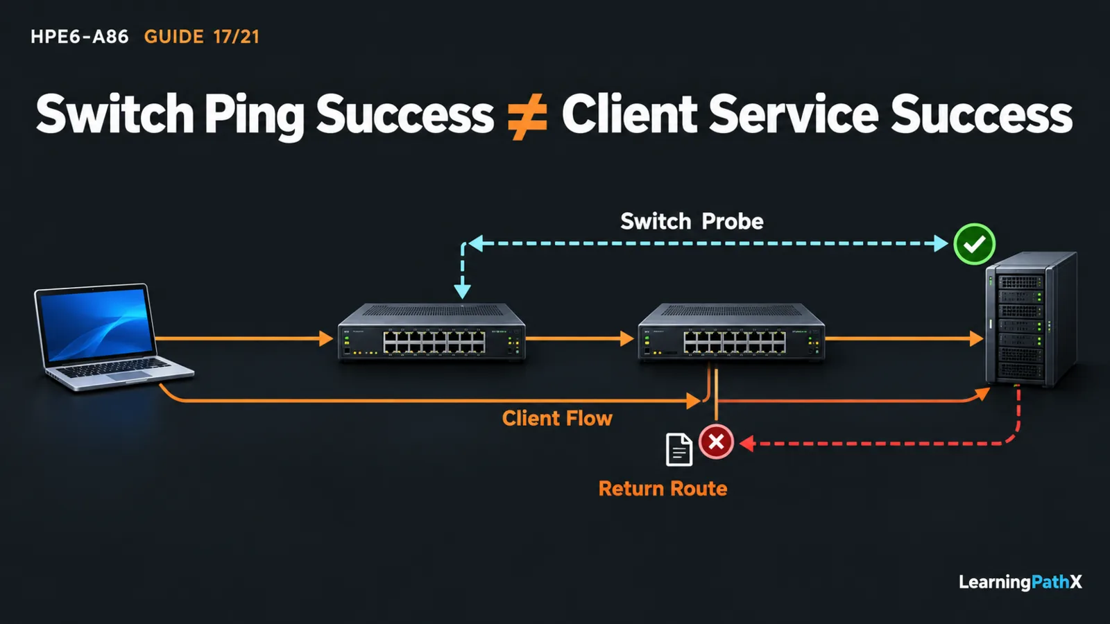
Isolate a failed network path by fixing the source, destination, service and management context, reproducing the symptom, and following evidence from the physical link through local forwarding, neighbor resolution, routing, return traffic and policy. At each stage, identify what the observation proves before changing one supported cause. Troubleshooting switched and routed connectivity becomes unreliable when several settings change before the original failure is understood.
This workflow uses AOS-CX 10.13 on CX 6300. Its original example follows a client toward a remote server; observations and outcomes are illustrative conditions to check, not an executed incident or invented command output. Use authorized tests, retain recovery access, and preserve evidence before clearing state, restarting a device or changing configuration.
Troubleshooting Methodology: Define One Failing Exchange
Record the affected source and destination, service, start time, reproducibility and any known-good comparison. Distinguish all clients failing from one client failing, and an application failure from a failed echo test. Record the actual Internet Protocol version 4 (IPv4) addresses, masks, gateways, virtual local area network (VLAN) membership and virtual routing and forwarding (VRF) context.
For the example, client 192.0.2.10/24 uses gateway A at 192.0.2.1. A reaches B through transit 10.0.0.1/30 to 10.0.0.2/30. Server 203.0.113.10/24 uses B at 203.0.113.1 as its gateway. The intended design routes the server prefix through B and the client prefix back through A. This is a bounded troubleshooting model, not a complete deployment procedure.
Save current configuration, relevant events, interface counters and the test's time/source/context. Compare with a known baseline where available. Ask what changed, but do not assume that the most recent change must be the cause.
Follow the Forwarding Evidence in Order
| Stage | Evidence to compare | Limit of the observation |
|---|---|---|
| Physical link | Administrative and operational state, media, negotiated speed, error changes | An up link does not establish correct VLAN membership. |
| Layer 2 path | Access/native/allowed membership and spanning-tree forwarding state | Configuration alone does not prove frames follow that path. |
| Learned forwarding | Media Access Control (MAC) entries in the intended VLAN | A learned source address does not prove a destination reply. |
| Local neighbor | Address Resolution Protocol (ARP) mapping for the selected next hop | A mapping does not prove the remote application is reachable. |
| Routed path | Selected destination route, next-hop reachability and return route | A forward route does not supply the reverse route automatically. |
| Policy and endpoint | Applied scope/direction, relevant matches, host firewall and service state | One permitted probe does not establish every application flow. |
Start at the affected host's actual attachment. Confirm the port identity rather than trusting a cable label. Link Layer Discovery Protocol (LLDP) helps identify a neighboring switch and port; it cannot establish that the affected VLAN passes over that adjacency.
For a redundant path, distinguish an expected blocked spanning-tree port from a failed port. For Link Aggregation Control Protocol (LACP), verify the intended partner and negotiated forwarding members, not only link lights. If Virtual Switching Framework (VSF) is involved, confirm the relevant member and stack path are healthy. These are evidence checks, not instructions to rebuild those technologies during an incident.
For this example, documented manager-context observations include:
switch# show interface 1/1/1
switch# show vlan port 1/1/1
switch# show mac-address-table dynamic vlan 10
switch# show arp vrf default
switch# show ip route
Port 1/1/1 and VLAN 10 are illustrative client attachments. Follow the actual path across every required interface and peer. A client sends remote traffic toward its gateway's local address; do not search the client's local VLAN for the remote server's MAC address.
Interpret Probe Failures Before Blaming the Destination
Use the command-line interface (CLI) in the intended VRF, with a deliberate source. The matching Diagnostics Guide documents these different failure meanings:
- An Operation not permitted ping message can indicate that a local control-plane access control list (ACL) blocked the request before transmission. Inspect the relevant policy; do not remove protection merely to obtain a reply.
- Network is unreachable can indicate a missing route or usable interface, incorrect addressing, or a forgotten management-VRF selection. It is not proof that the far endpoint is down.
- A timeout establishes that the expected reply did not arrive. The request path, return path, filtering and endpoint response still require investigation.
For an authorized short test from A, use an address actually assigned to A in the chosen context:
switch# ping 203.0.113.10 vrf default source 192.0.2.1
switch# traceroute 203.0.113.10 maxttl 4 probes 1 vrf default source 192.0.2.1
The ping command's documented default is five requests; the traceroute example caps the explored hops and probes. Select limits appropriate to the known path. A missing traceroute response is not alone proof that the last responding device is faulty: probe responses and application forwarding can be subject to different policy. A switch-originated test also does not reproduce every property of the client's traffic.
Test One Explanation Against the Example
Suppose the client reaches its gateway, the documented local VLAN path is correct, A selects B for the remote prefix, and B reaches its directly attached server. Those conditions narrow the search; they do not establish a complete round trip.
Next inspect B's selected route toward 192.0.2.10. If the required client-prefix route is missing and no valid alternative exists, B lacks the intended return decision. This explains why a probe sourced from A's transit address could succeed while the actual client exchange fails: the transit subnet and client subnet have different return-route requirements.
Check that hypothesis against configuration, selected routes and the test's actual source. Also inspect relevant policy and endpoint state before declaring the route the sole fault. Keep the distinction between a plausible explanation and evidence-supported diagnosis explicit.
Resolve, Retest and Recover
If the approved design and evidence confirm that a return route was removed, restore that one intended route through the authorized change process. Verify the reachable next hop and record the prior configuration and recovery action first. Use HPE6-A86: Implementing Inter-VLAN and Static Routing for the exact configuration rather than inventing an emergency route or default.
Repeat the original client-to-server service test, the reverse-direction check where applicable, and the selected route/neighbor observations. Check an unaffected flow and management access for regression. A successful switch ping alone is insufficient closure.
If the change does not produce the expected evidence, stop, restore the recorded prior state through the retained recovery path and reassess. Avoid clearing tables, disabling several policies or rebooting as an unexplained next step. Those actions can destroy the evidence needed to distinguish competing causes.
For HPE6-A86, useful troubleshooting ends with a causal account: the failed exchange, the observation that narrowed it, the corrected condition and the repeated acceptance result. Preserve that account so a recurring symptom can be compared with evidence rather than another round of guesses.
Authoritative Sources
- AOS-CX 10.13 Fundamentals Guide
- AOS-CX 10.13 Layer-2 Bridging Guide
- AOS-CX 10.13 Link Aggregation Guide
- AOS-CX 10.13 Virtual Switching Framework Guide
- AOS-CX 10.13 IP Routing Guide
- AOS-CX 10.13 IP Services Guide
- AOS-CX 10.13 Diagnostics and Supportability Guide
- AOS-CX 10.13 ACLs and Classifier Policies Guide
- HPE Network Switching Associate Exam