
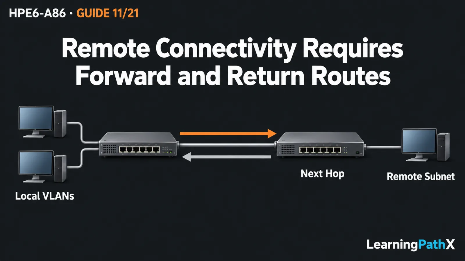
To implement routing between virtual local area networks (VLANs), give each VLAN an addressed switched virtual interface (SVI) and make that address its hosts' gateway. Connected routes handle these local subnets for inter-VLAN routing. To reach a remote subnet, configure a static route through a reachable neighboring router and configure the corresponding return routes there. Validate interface state, selected routes and traffic in both directions; entering a route command alone does not prove connectivity.
This original procedure uses two standalone CX 6300 switches running AOS-CX 10.13 and Internet Protocol version 4 (IPv4). All data interfaces use the default virtual routing and forwarding (VRF) context, separate from dedicated management. It assumes the addressing and access-port skills from the prerequisite lessons; it does not derive subnet masks or configure a dynamic routing protocol. Commands illustrate verified syntax, not an executed deployment.
Architecture Overview: Separate Gateway and Next Hop
Switch A routes between VLANs 10 and 20. Its port 1/1/48 is a routed transit link to switch B, which routes to one remote host. The transit is a Layer 3 interface rather than a VLAN trunk. Confirm that these example ports and media are supported on the actual devices.
| Attachment | Host address | Host gateway | Switch interface address |
|---|---|---|---|
| A port 1/1/1, access VLAN 10 | 192.0.2.10/24 | 192.0.2.1 | A SVI 10: 192.0.2.1/24 |
| A port 1/1/2, access VLAN 20 | 198.51.100.10/24 | 198.51.100.1 | A SVI 20: 198.51.100.1/24 |
| B port 1/1/1, routed host link | 203.0.113.10/24 | 203.0.113.1 | B port 1/1/1: 203.0.113.1/24 |
| A–B transit, port 1/1/48 at each end | No host | Not applicable | A: 10.0.0.1/30; B: 10.0.0.2/30 |
These are illustrative isolated-lab addresses. A host's gateway is on its own subnet. A's next hop toward 203.0.113.0/24 is B's transit address, not the remote host's gateway and not A's own address. An SVI supplies a Layer 3 attachment to a VLAN; the access port still performs Layer 2 membership.
Preserve Recovery Before Changing Forwarding
Use exclusive lab ownership, three test hosts and retained console access to both switches. Disconnect all lab data cables initially and keep production disconnected throughout. Start with reserved ports, unused example VLANs and no conflicting routes, filters or interface configuration. Do not repurpose an existing management path. Verify authorized management access independently before proceeding.
Record each device's baseline and create and inspect its own checkpoint from manager context:
switch# copy running-config checkpoint pre-route11
switch# show checkpoint pre-route11
Keep startup configuration unchanged during the exercise. A checkpoint can replace all intervening running changes during recovery, so shared concurrent changes would make this rollback unsafe. Routing the VLANs also permits communication between them when no policy blocks it; use this isolated topology rather than treating VLAN separation alone as an access-control policy.
Configure A's Local VLAN Gateways
On A, create the VLANs before their SVIs, then configure the two access ports:
switch# config
switch(config)# vlan 10
switch(config-vlan-10)# exit
switch(config)# vlan 20
switch(config-vlan-20)# exit
switch(config)# interface vlan 10
switch(config-if-vlan)# ip address 192.0.2.1/24
switch(config-if-vlan)# no shutdown
switch(config-if-vlan)# exit
switch(config)# interface vlan 20
switch(config-if-vlan)# ip address 198.51.100.1/24
switch(config-if-vlan)# no shutdown
switch(config-if-vlan)# exit
switch(config)# interface 1/1/1
switch(config-if)# no routing
switch(config-if)# vlan access 10
switch(config-if)# no shutdown
switch(config-if)# exit
switch(config)# interface 1/1/2
switch(config-if)# no routing
switch(config-if)# vlan access 20
switch(config-if)# no shutdown
switch(config-if)# end
Attach and address the two local hosts according to the table, using their operating systems' network settings. Permit the intended test traffic through host firewalls. Check that the access ports and SVIs are operational; a configured SVI address is not proof that a working Layer 2 member path exists.
The active addressed SVIs should supply connected routes for 192.0.2.0/24 and 198.51.100.0/24, plus local routes for the switch's own addresses. A therefore needs no static route between those two directly attached networks. Test each host's own gateway, then host-to-host traffic across A before adding the remote path.
Build the Routed Transit and Remote Attachment
With the transit cable still disconnected, configure A:
switch# config
switch(config)# interface 1/1/48
switch(config-if)# shutdown
switch(config-if)# routing
switch(config-if)# ip address 10.0.0.1/30
switch(config-if)# exit
switch(config)# ip route 203.0.113.0/24 10.0.0.2
switch(config)# end
On B, prepare its transit, remote host interface and return routes:
switch# config
switch(config)# interface 1/1/48
switch(config-if)# shutdown
switch(config-if)# routing
switch(config-if)# ip address 10.0.0.2/30
switch(config-if)# exit
switch(config)# interface 1/1/1
switch(config-if)# routing
switch(config-if)# ip address 203.0.113.1/24
switch(config-if)# no shutdown
switch(config-if)# exit
switch(config)# ip route 192.0.2.0/24 10.0.0.1
switch(config)# ip route 198.51.100.0/24 10.0.0.1
switch(config)# end
Configure and connect B's host. Inspect both prepared configurations, connect the single transit cable, then issue no shutdown in port 1/1/48's interface context on both devices. The routing command changes a physical port to Layer 3 operation; do not add access or trunk membership to this transit.
Static routes express destination prefixes and forwarding next hops. They do not tell the remote router how to return traffic automatically. B's two routes make those return decisions explicit, while B's remote subnet is directly connected.
Validate Routes and End-to-End Traffic
From manager context, inspect both switches:
switch# show running-config
switch# show interface 1/1/48
switch# show ip route
On A, also inspect show interface vlan 10, show interface vlan 20 and show vlan. Confirm addresses, access membership, operational state and the default VRF. Expect connected transit and local networks, with the remote prefix selected through 10.0.0.2. On B, expect connected transit/remote networks and both return prefixes through 10.0.0.1. These are acceptance expectations, not reported output.
Test B's host against its gateway, then test from each A-side host to 203.0.113.10 and from the remote host back to both local hosts. This exercises more than a switch-originated probe, whose source address can use a different return route. A failure calls for comparing the matching destination route, reachable next hop, host gateway and return path individually. A selected route still cannot prove neighbor resolution or endpoint firewall permission.
A default route, 0.0.0.0/0, is a fallback when no more-specific destination route matches. This bounded topology uses explicit remote routes, so it needs no default. In a design with an approved upstream, a default must point toward a router that can handle those destinations; reciprocal defaults between these two switches could loop unknown traffic. Do not add one as a generic connectivity fix.
Roll Back or Retain the Accepted State
If acceptance fails, preserve evidence and use the consoles rather than changing several routes at once. For cleanup, disconnect the lab data cables, restore each switch's own baseline with checkpoint rollback pre-route11 from manager context, and verify original interfaces, routes and management access. Restore host settings separately. Reconnect only the original intended topology.
If retaining the lab, first confirm all planned traffic and management checks, then use copy running-config startup-config and inspect the saved state. Inter-VLAN and static routing are complete only when the local gateways, forward route and remote return path agree with observed host communication.