
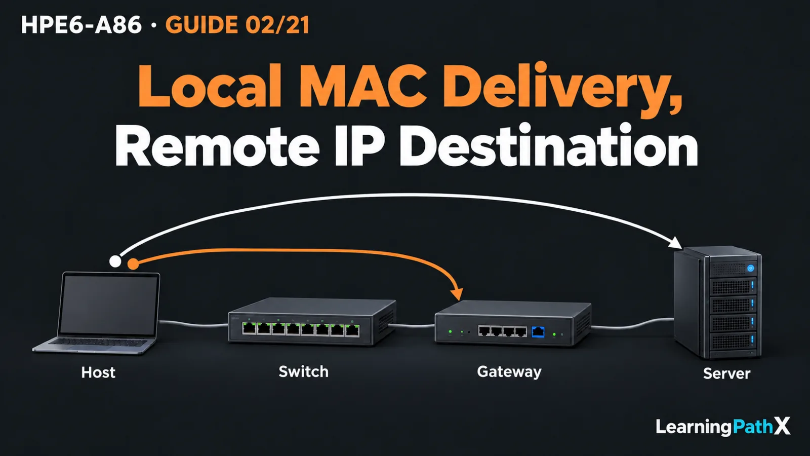
Following an Ethernet packet through the network layers means separating three decisions: how a signal crosses one link, how a frame reaches the next device on its local network, and how an Internet Protocol (IP) packet reaches a remote network. Transmission Control Protocol (TCP) or User Datagram Protocol (UDP) then provides communication between applications on the endpoint hosts. An Ethernet switch usually makes the local forwarding decision using a destination Media Access Control (MAC) address; a router selects a next hop using the destination IP address.
This distinction explains why a working cable, a learned MAC address and a successful application connection are different observations. The example below follows a host reaching a server through an HPE Aruba Networking CX 6300 Switch Series device and a router. Product observations use AOS-CX 10.13 as the teaching baseline; the protocol explanation is general networking knowledge supported by the listed standards. It is an illustrative packet journey, not an executed lab.
Architecture Overview: One Application, Several Layers
The Open Systems Interconnection (OSI) reference model names seven layers: Physical, Data Link, Network, Transport, Session, Presentation and Application, from lowest to highest. It gives engineers a common vocabulary for locating responsibilities. It does not require seven separate headers in every packet.
The Internet protocol suite groups responsibilities differently. For this journey, think of application data carried by a transport protocol, inside an IP packet, inside a link-layer frame. A transmitter encodes that frame into signals suitable for the physical medium. At the receiver, the relevant layers interpret their information and deliver the payload onward.
Suppose a workstation has address 192.0.2.10/24 and uses 192.0.2.1 as its gateway. It opens a TCP connection to a server at 198.51.100.20 on port 443. Assume the address plan, routes and return path are correct, the workstation and gateway share a virtual local area network (VLAN), and no address translation occurs. The subnet calculation and VLAN configuration are separate tasks; here their results are given inputs.
Core Components and Their Decisions
Physical Media Carry Signals
Copper cabling carries electrical signals; fiber carries optical signals. Ports, transceivers and the connecting medium must form a compatible link. A link indication establishes a local physical relationship, not proof that the faraway server or application is reachable.
Use the selected switch and transceiver documentation for a real installation. A general statement that a switch supports fiber does not establish the supported optic, cable type, speed or distance for a particular port. Those details cannot be inferred from this conceptual example.
Ethernet Delivers a Frame Locally
An Ethernet frame identifies a source and destination MAC address. A switch learns where source MAC addresses are reachable and uses its MAC address table to select an outgoing port for a known destination in the relevant VLAN.
If the destination is unknown, normal Layer 2 forwarding floods the frame to eligible ports in that VLAN, excluding the arrival port. Broadcast delivery also stays within the Layer 2 broadcast domain. VLAN membership and forwarding state therefore matter even when all cables are connected. A learned source address describes where traffic was seen; it does not prove that the destination has replied.
IP Selects the Remote Path
The workstation determines that the server is outside its connected subnet and selects its configured gateway. It needs local delivery to that gateway before the remote IP destination can be reached. Address Resolution Protocol (ARP) supplies the mapping between an on-link IP version 4 address and its Ethernet address.
The router receives the frame, examines the IP destination and selects a route and next hop. A Layer 3 capable switch can perform routing when configured for that role; the word switch does not mean that every interface or deployment is limited to Layer 2.
Transport Identifies Application Conversations
TCP provides a connection-oriented, reliable byte stream with ordering and flow control. UDP provides a connectionless datagram service. UDP itself does not add TCP's delivery and ordering guarantees; an application can implement additional behavior above it.
Transport ports distinguish application endpoints. In this example, the server listens on destination TCP port 443 while the workstation uses its own source port. TCP reliability does not encrypt the payload: secure application communication requires the appropriate higher-layer protection. Neither a port number nor an established TCP connection alone proves that the application completed its work.
How the Packet Moves Through the Example
First, the workstation resolves the gateway's MAC address if it lacks a usable cached mapping. Its ARP request is broadcast on the local VLAN. The gateway's reply provides the local mapping needed for subsequent frames. The workstation resolves the gateway, rather than sending a local ARP broadcast to find the remote server.
Next, the workstation sends a frame with its own source MAC address and the gateway's destination MAC address. Inside that frame, the IP destination remains 198.51.100.20. The Ethernet destination and IP destination describe different parts of the journey: the next local recipient and the final IP recipient.
The CX switch learns the workstation's source MAC address and forwards toward the gateway according to its Layer 2 table and VLAN forwarding rules. It does not replace the remote server's IP address with the gateway address.
The router removes the received link-layer encapsulation, selects the outgoing route and builds an appropriate frame for the next link. On an Ethernet next link, that frame uses the router's outgoing source MAC address and the next hop's destination MAC address. Thus Ethernet addresses change across routed hops, while the original IP endpoint addresses remain the same under this example's no-translation assumption. The IP header is not entirely unchanged: routing also processes fields such as Time to Live.
The server receives the packet through the remaining path and processes the transport exchange. Its response needs a valid return path. A request leaving the workstation does not establish that the response can return through routing and policy controls.
Design Considerations and Common Mistakes
Keep observations tied to the question they answer. Interface state and error counters concern the local link. VLAN membership and MAC learning concern local frame forwarding. ARP concerns an on-link neighbor mapping. Route selection concerns the IP next hop. Application behavior also depends on endpoint transport and service state.
Avoid treating these observations as interchangeable. A MAC table entry is not an IP route; an ARP entry is not a TCP connection; and a link that is up is not proof of correct VLAN membership. Likewise, an ordinary Layer 2 switch does not need to establish a TCP session merely to forward the Ethernet frames carrying one.
Certification Relevance and Conclusion
HPE6-A86 connects layering, media, Ethernet, IP and transport concepts to practical switching work. Explaining which address is inspected, which device makes each decision and what changes at a routed boundary provides a useful foundation for later configuration and fault isolation.
For any proposed path, follow the encapsulation and name the next decision explicitly. This makes a packet journey understandable without confusing physical connectivity, local forwarding, routing and application success.