
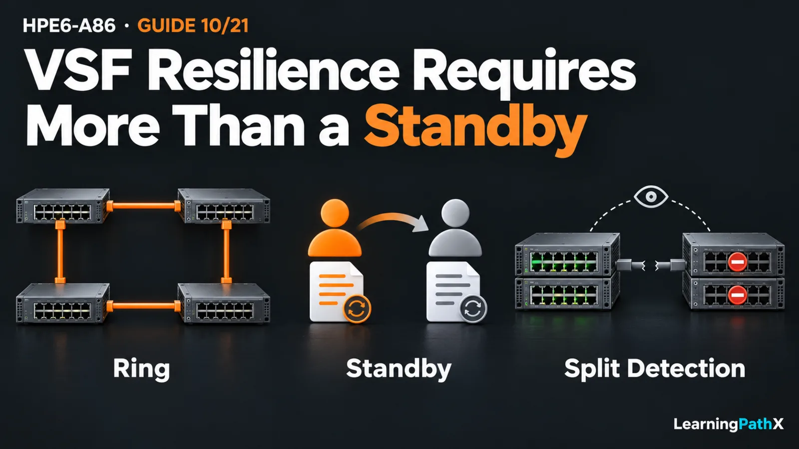
A CX 6300 Virtual Switching Framework (VSF) stack combines member switches into one logical switch with a shared control plane. The conductor manages that logical device; a configured standby holds synchronized configuration and can assume the conductor role when required. Validate resilience by checking member roles, stack connectivity and split-detection readiness, then observing a controlled failure and recovery. One working management session does not establish that every member and service path is healthy.
Designing and validating a CX 6300 VSF stack therefore requires both a logical-device model and a physical failure model. This article uses AOS-CX 10.13 and an original four-member ring example. It explains architecture and evidence rather than prescribing unverified cabling or provisioning commands. Virtual Switching Extension (VSX) is a separate technology; its design and procedures are outside this VSF discussion.
Architecture Overview: One Device Across Several Members
Each member contributes physical ports, while the stack presents a single configuration and management system. A port's member identity still matters: a logical switch can have a failed physical member, and devices attached only to that member can lose connectivity even if the remaining stack is operating.
The conductor runs the control plane and manages the members. The standby maintains a synchronized configuration copy and provides the alternate control role. Other members do not become independent protocol owners merely because their ports forward traffic. This distinction helps explain why member presence, conductor availability and endpoint connectivity are separate observations.
Record the primary and configured secondary member identities as well as the current conductor and standby roles. A label on the chassis is a physical reference; an operational role describes current behavior. Keeping both avoids confusing a recovered member with an assumption that every role must immediately match an earlier screenshot.
Physical Topology Determines Which Failures Disconnect Members
VSF links carry connectivity between stack members. They are part of the stack architecture, not ordinary user-facing links that can be reassigned without changing the failure model.
| Design element | What it contributes | What it does not establish |
|---|---|---|
| Ring topology | An alternate path after a single stack-link failure | Survival of every simultaneous failure or continued access to ports on a failed member |
| Chain topology | Connectivity along one path between members | An alternate path when that path is broken |
| Standby role | An alternate conductor role with synchronized configuration | A repair for missing physical stack paths |
| Split detection | A mechanism to mitigate competing active fragments | Continued service on every fragment after a split |
In the example, connect four already compatible members in a logical ring A–B–C–D–A, with A initially conductor and C standby. A single failure of B–C leaves an alternate path through A and D. The topology is degraded even if all members remain reachable. Treat that as reduced resilience requiring repair, not proof that the original ring is still intact.
A chain has only one path between a pair of members. A break can partition it. The difference is structural: a second physical path changes which failures separate members; assigning a standby does not create that path.
Split Detection Resolves a Different Problem
A partition that places conductor and standby in different fragments can allow both fragments to act as a logical switch. Competing identities can disrupt the surrounding network. Split detection addresses this risk rather than reconnecting the broken stack.
The documented management-based mechanism uses the primary and secondary management interfaces on the same Layer 2 network, or directly connected to each other. When the secondary fragment discovers that the primary fragment remains operational, its non-VSF front-panel interfaces are brought down. That deliberate loss of forwarding on the losing fragment mitigates duplicate active identities.
Include this management path in the design and validation record. A configured split-detection setting alone does not prove its peer path works. Also distinguish an isolated stack-link failure from loss of that detection path; combining failures without a defined expectation makes the result difficult to interpret.
Establish Compatibility Before Adding a Member
Check exact stock keeping units (SKUs), supported stack-link interfaces, media, speed combinations and the applicable software restrictions in the matching guide. The current CX portfolio identifies product roles; it is not a historical AOS-CX 10.13 compatibility matrix. Do not derive a universal mixed-model or link-speed rule from the CX 6300 family name.
Members operate with a common software image. The documented joining process can synchronize a different member image and reboot that member before it joins, but automated synchronization has version-boundary restrictions. Verify the actual starting and target versions rather than treating synchronization as permission to join any old image.
For a planned expansion, identify the intended member number and role, reserve the required ports, preserve recovery access and define how attached devices will be affected. Joining is an operational change, not merely connecting another cable. This article does not establish an uninterrupted-upgrade guarantee or a universal member limit.
Validate the Architecture Before and During One Failure
Use an isolated authorized stack or an approved maintenance window. Before disturbing anything, save the intended topology and configuration record, identify the exact test link, and retain independent recovery access. Agree on stop conditions and the physical restoration step.
From manager context, the documented observation commands include:
switch# show vsf
switch# show vsf detail
switch# show vsf link
switch# show vsf topology
Use those views to compare actual members, roles, topology, split state and link peers with the design. Record software and compatibility evidence separately. Then establish representative endpoint and upstream traffic paths, including traffic that must cross members. A stack-status view alone cannot prove those paths work.
For the four-member ring example, interrupt only the preselected B–C link after confirming the alternate path is healthy. Observe whether all expected members remain connected, which topology and link states are reported, and whether the selected service tests still meet their agreed acceptance criteria. Do not introduce a second fault while the ring is degraded.
This is an original test design, not a reported result. A link test does not validate conductor takeover, member failure or split detection. Those require separately approved scenarios, explicit expectations and fresh baselines; a split test can deliberately disable a fragment's service ports.
Recover and Judge the Result
Restore the interrupted link and verify the intended ring, expected members and roles, healthy peer links and absence of an unexpected split. Repeat the same service checks used before the fault. Keep observations if the topology or service result differs from the baseline, and investigate before calling the architecture resilient.
If restoration fails, stop the exercise, preserve recovery access and follow the guide's link/member diagnosis and recovery process. Avoid adding members, resetting devices or combining configuration changes while the failure's cause remains unclear.
For HPE6-A86, the useful architecture synthesis is to connect logical simplicity with explicit physical dependencies. A ring, standby and split detection each solve a different problem. Resilience is demonstrated by the expected response and recovered service for a defined failure, not by the existence of several switches in a stack.
Authoritative Sources
- AOS-CX 10.13 Virtual Switching Framework Guide
- HPE Aruba Networking CX switches
- HPE Network Switching Associate Exam