
Introduction
Configure a virtual local area network (VLAN) path by assigning untagged endpoint ports to their intended access VLANs and carrying those VLANs across an explicitly restricted trunk. Match the trunk's native VLAN and tagging behavior at both ends. Then verify configuration, Media Access Control (MAC) learning and endpoint traffic separately; Link Layer Discovery Protocol (LLDP) identifies the adjacent device but does not prove that a particular VLAN forwards correctly.
This procedure uses an original isolated two-switch lab on CX 6300 with AOS-CX 10.13. It connects VLAN membership, Institute of Electrical and Electronics Engineers (IEEE) 802.1Q tagging and LLDP validation without configuring spanning tree, link aggregation or inter-VLAN routing. Commands below are documented configuration examples, not a transcript of an executed lab.
Architecture Overview and Safety Boundary
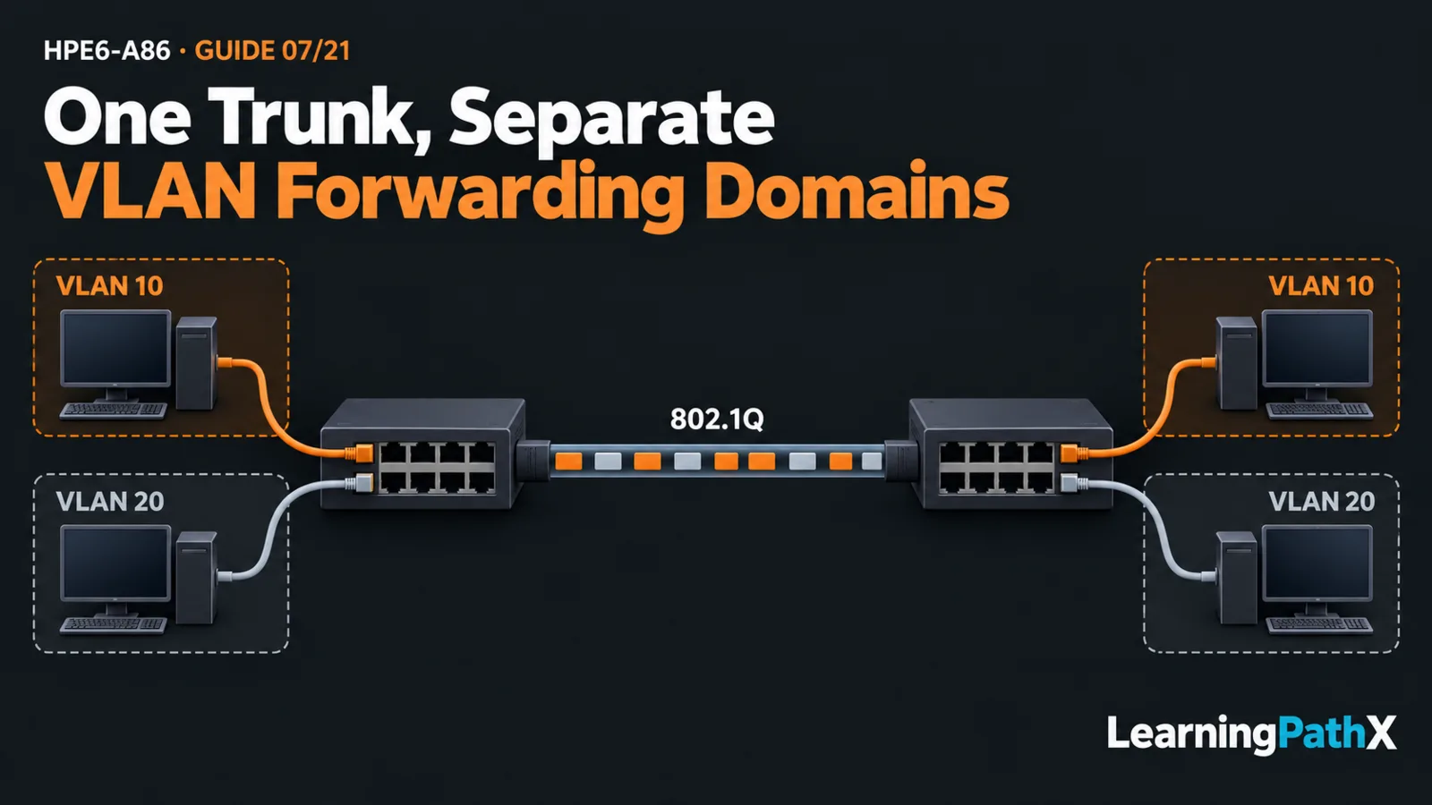
Use two authorized standalone lab switches, A and B, joined by one cable between their example ports 1/1/48. Confirm that the selected hardware actually provides those interfaces; substitute the documented port identifiers when necessary. Connect two ordinary untagged hosts to each switch:
| Role on each switch | Port | VLAN | Host addresses: A / B |
|---|---|---|---|
| First endpoint | 1/1/1 | 10 | 192.0.2.10/24 / 192.0.2.11/24 |
| Second endpoint | 1/1/2 | 20 | 198.51.100.10/24 / 198.51.100.11/24 |
| Single inter-switch link | 1/1/48 | Tagged 10 and 20; native 99 | No host addressing |
The addresses are illustrative. Use no routed interfaces or gateway for these same-subnet tests. VLAN 99 provides an explicitly matched native VLAN with no lab endpoints; it is not a management network or a complete security policy.
Keep this topology disconnected from production and free of additional inter-switch links. VLAN changes can interrupt management or expose unintended traffic. Maintain console access to both devices, reserve the ports, record existing settings and coordinate exclusive lab ownership. Do not change an interface that carries your only recovery connection.
Core Concepts: Access, Trunk and Native Membership
An access port assigns the example host's untagged traffic to one VLAN. Across the uplink, the IEEE 802.1Q tagging mechanism identifies VLAN membership so VLANs 10 and 20 can share the physical link while retaining separate forwarding domains.
The native VLAN controls the trunk's untagged treatment. This lab uses native VLAN 99 without the native-tag option on both switches. A mismatched native VLAN can classify untagged traffic differently at each end. Matching the native value does not replace checking the allowed VLAN list.
AOS-CX requires non-routed Layer 2 interfaces for this membership. The documented no routing command establishes that mode; do not transfer ArubaOS-Switch configuration syntax into this AOS-CX procedure.
Prepare Recovery and Configure Membership
Save a Known Baseline
At the Manager prompt on each switch, create and inspect a checkpoint using an unused name:
switch# copy running-config checkpoint pre-vlan07
switch# show checkpoint pre-vlan07
Confirm that the checkpoint exists and represents the intended baseline before continuing. Record the management path and original port state. A checkpoint is a configuration recovery tool, not proof that the intended design is safe.
Configure Both Switches with the Uplink Shut Down
Apply the following on both lab switches. The prompt transitions identify global configuration, VLAN and interface contexts; they are not claimed observed output.
switch# config
switch(config)# lldp
switch(config)# vlan 10
switch(config-vlan-10)# exit
switch(config)# vlan 20
switch(config-vlan-20)# exit
switch(config)# vlan 99
switch(config-vlan-99)# exit
switch(config)# interface 1/1/1
switch(config-if)# shutdown
switch(config-if)# no routing
switch(config-if)# vlan access 10
switch(config-if)# no shutdown
switch(config-if)# exit
switch(config)# interface 1/1/2
switch(config-if)# shutdown
switch(config-if)# no routing
switch(config-if)# vlan access 20
switch(config-if)# no shutdown
switch(config-if)# exit
switch(config)# interface 1/1/48
switch(config-if)# shutdown
switch(config-if)# no routing
switch(config-if)# vlan trunk native 99
switch(config-if)# vlan trunk allowed 10,20,99
switch(config-if)# lldp transmit
switch(config-if)# lldp receive
switch(config-if)# end
The order matters: defining a native VLAN automatically enables vlan trunk allowed all under the documented 10.13 behavior. Apply the explicit allowed list after the native command. Keeping the uplink shut down while preparing both ends avoids forwarding through that intermediate unrestricted state.
After confirming both configurations, enable the uplink on each switch:
switch# config
switch(config)# interface 1/1/48
switch(config-if)# no shutdown
switch(config-if)# end
Validate the Path in Separate Layers
From Manager context, collect these observations on both switches:
switch# show vlan port 1/1/1
switch# show vlan port 1/1/2
switch# show vlan port 1/1/48
switch# show lldp configuration 1/1/48
switch# show lldp neighbor-info 1/1/48
switch# show mac-address-table dynamic vlan 10
switch# show mac-address-table dynamic vlan 20
First compare access membership, native treatment and trunk membership against the table. Verify LLDP transmission/reception settings and the expected peer identity and port. An LLDP neighbor can be present while VLAN 20 is missing from an allowed list, so neighbor discovery alone is insufficient.
Generate permitted test traffic between the two VLAN 10 hosts, then between the two VLAN 20 hosts. Account for host firewalls and endpoint state when choosing the test. Inspect dynamic MAC entries after traffic: each local host should be associated with its access port, and the remote host with the uplink, in the correct VLAN. These are acceptance expectations, not invented observed results.
Success means both same-VLAN pairs communicate and their membership, neighbor and learned-address evidence agrees with the intended path. Do not expect communication between the two VLANs: this lab deliberately supplies no routing. A failed cross-VLAN test alone is not a complete security assessment.
Common Mistakes, Rollback and Conclusion
If only one same-VLAN pair fails, compare its access membership and allowed list at both ends before changing several settings. A correct VLAN number on one switch does not establish the peer's configuration. Preserve observations before clearing tables, and do not treat an empty MAC table before traffic as proof of a fault.
For failure recovery or lab cleanup, disconnect test hosts and the inter-switch cable, then restore each switch's own baseline through console access:
switch# checkpoint rollback pre-vlan07
Rollback replaces the running configuration and can remove all intervening changes; use it only under the exclusive lab ownership established above. Recheck original port and management state afterward. Leave startup configuration unchanged during the temporary exercise. Retaining a validated design requires a separate explicit decision to save it.
VLAN validation joins three kinds of evidence: intended configuration, learned forwarding state and actual endpoint behavior. Keeping those separate makes access and tagged-uplink results explainable without mistaking neighbor discovery for end-to-end success.
Authoritative Sources
- AOS-CX 10.13 Fundamentals Guide
- AOS-CX 10.13 Layer-2 Bridging Guide
- HPE Network Switching Associate Exam