
Configure Multiple-instance Spanning Tree Protocol (MSTP) consistently on every switch in the intended region: match the region name, revision and complete virtual local area network (VLAN)-to-instance mapping, then choose root priorities and classify genuine host-facing edge ports. Validate the region, elected root and each redundant port's role before testing failure and recovery. An enabled spanning tree alone does not prove that the intended topology is operating.
This procedure uses two isolated, standalone CX 6300 switches running AOS-CX 10.13. It extends the access/trunk foundation in HPE6-A86: Configuring VLAN Membership, 802.1Q Tagging and LLDP Validation. Commands illustrate documented syntax and original lab values; they are not a transcript of an executed test. Retain console access to both switches, and keep the lab disconnected from production.
Architecture Overview: Rapid Convergence and Instances
Spanning Tree Protocol (STP) prevents a redundant Layer 2 topology from forwarding frames around a loop. Rapid Spanning Tree Protocol (RSTP) improves convergence after topology changes. MSTP supports rapid convergence and maps VLAN groups to multiple spanning tree instances, each with its own forwarding topology. On this release, the documented mode command selects MSTP or Rapid Per VLAN Spanning Tree (RPVST); this procedure explicitly selects MSTP rather than inventing a separate RSTP mode command.
Switches exchange Bridge Protocol Data Units (BPDUs) to calculate the tree. A root port provides a non-root switch's selected path toward the root; a designated port forwards for its segment, while an alternate path can remain blocked until needed. A port's role and forwarding state are separate observations. MSTP neither combines links into a bandwidth bundle nor combines switches into one control plane.
Prepare the Isolated Topology
Use switches A and B, with two independent full-duplex links: A port 1/1/47 to B port 1/1/47, and A port 1/1/48 to B port 1/1/48. Verify these interfaces exist and support the intended media on the actual models. Reserve them exclusively for this exercise; neither belongs to an aggregate or a stack link.
On both switches, retain the prerequisite lesson's VLANs 10, 20 and 99. Both uplinks must be Layer 2 trunks carrying exactly 10, 20 and 99, with native VLAN 99 matching at both ends. Prepare the second trunk using the same documented VLAN procedure. Keep both cables disconnected and both uplinks administratively shut down while preparing settings. An unrestricted or mismatched trunk is not repaired by spanning tree.
Connect one ordinary, non-bridging endpoint to each switch's access port 1/1/1 in VLAN 10. For example, use Internet Protocol version 4 (IPv4) addresses 192.0.2.10/24 and 192.0.2.11/24 with host firewalls permitting the chosen test. VLAN 20 shares the tree; VLAN 99 has no endpoint in this example. Record the original spanning tree, VLAN and interface configuration and the prerequisite lesson's recovery baseline before changing anything. Preserve startup configuration during testing.
Configure a Consistent MSTP Region
From manager context, enter configuration mode and apply this common block on both switches while the uplinks remain disconnected and shut down:
switch# config
switch(config)# spanning-tree mode mstp
switch(config)# spanning-tree
switch(config)# spanning-tree config-name LAB-MSTP
switch(config)# spanning-tree config-revision 1
switch(config)# spanning-tree instance 1 vlan 10
switch(config)# spanning-tree instance 1 vlan 20
The second mapping command adds VLAN 20 to the existing instance. Both VLANs now use multiple spanning tree instance (MSTI) 1. Unmapped VLANs, including 99 here, remain in instance 0, associated with the common and internal spanning tree (CIST). The revision number identifies the intended region configuration; it does not automatically distribute or synchronize settings.
Verify the complete mapping on both devices, including mappings left by previous exercises. Identical names and revision numbers with different mappings still describe different regions. Stop and correct any unexpected configuration before connecting links.
Choose Roots and Protect Actual Edge Ports
In configuration context on A, set its priority for instance 0 and instance 1:
switch(config)# spanning-tree priority 0
switch(config)# spanning-tree instance 1 priority 0
On B, use the corresponding commands with priority multiplier 1 instead of 0. These switch-priority arguments are multipliers of 4096, not raw bridge-priority values. Lower priority wins; A is the intended root and B the secondary in this two-switch lab. Instance 0 uses the global priority command, whereas instance 1 uses the instance-specific command. Root placement should be deliberate rather than left to address-based tie-breaking.
On both switches, configure the known endpoint port and explicitly retain network-port behavior on both uplinks:
switch(config)# interface 1/1/1
switch(config-if)# spanning-tree port-type admin-edge
switch(config-if)# spanning-tree bpdu-guard
switch(config-if)# exit
switch(config)# interface 1/1/47
switch(config-if)# spanning-tree port-type admin-network
switch(config-if)# exit
switch(config)# interface 1/1/48
switch(config-if)# spanning-tree port-type admin-network
switch(config-if)# end
An administrative edge port transitions immediately to forwarding during tree establishment. BPDU guard disables that port if it receives a BPDU, helping detect an unexpected bridge attachment. Do not apply this endpoint assumption or guard policy to the inter-switch links, where BPDUs are expected. Administrative network mode examines received BPDUs and participates in normal spanning tree when a bridge is detected.
Validate Before Adding the Redundant Path
Run these manager-context commands on both devices:
switch# show spanning-tree mst-config
switch# show spanning-tree summary root
switch# show spanning-tree mst
Compare region name, revision, configuration digest and full instance mappings. Matching digests help validate mapping consistency; compare the other region fields separately. Confirm spanning tree is enabled in MSTP mode. With links still down, each isolated switch can identify itself as root, so this stage cannot yet prove A's election across the topology.
Connect only the 1/1/47 cable and enable that interface on both ends using no shutdown in its interface context. Recheck roots and port states after convergence. A should be root for instances 0 and 1; B should select its connected uplink as the root path. Test the two VLAN 10 endpoints before proceeding.
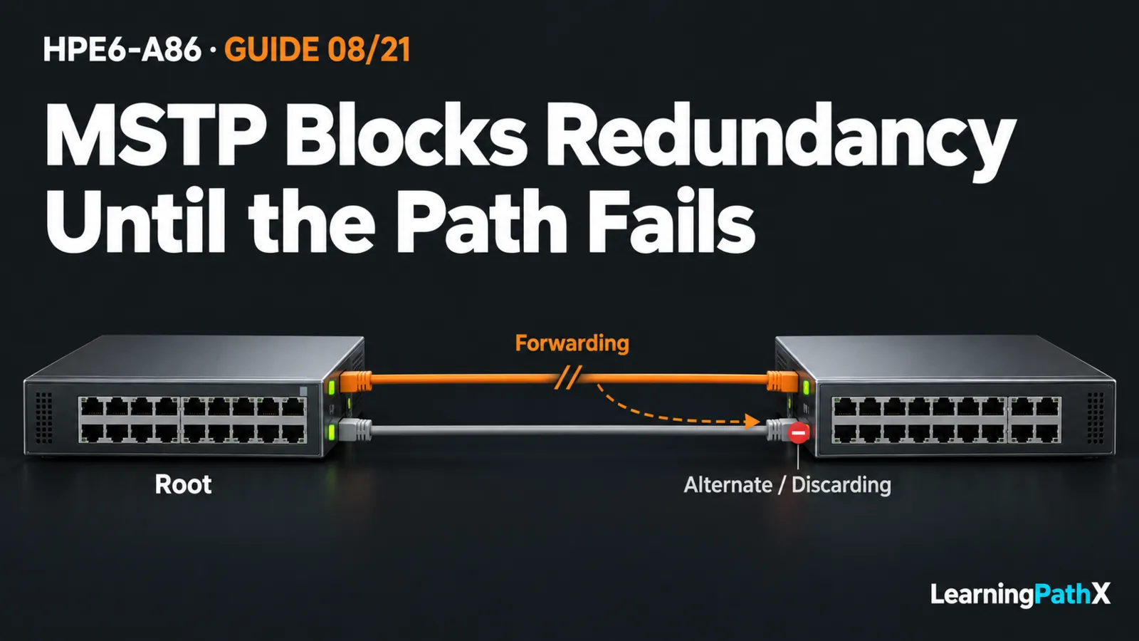
Next connect and enable 1/1/48 on both ends. Re-run the same observations. In this simple topology, A's inter-switch ports should be designated and forwarding, while B should have one root forwarding port and one alternate blocked path for instance 1. The display may label the blocked state as blocking or discarding. Do not assume which numbered port wins: cost and tie-breaking matter. Two physical links being up is insufficient evidence of a loop-free forwarding tree.
Prove Failure Recovery and Restore Safely
Record B's selected forwarding uplink, then shut down that interface in the isolated lab. Observe the remaining alternate path becoming the forwarding root path and repeat endpoint traffic tests after convergence. Record actual disruption; rapid convergence does not guarantee zero lost packets or a fixed recovery time. Restore the disabled interface with no shutdown, then recheck election, roles and connectivity.
If evidence differs from the intended design, disconnect the redundant link first. Use the retained consoles to compare region fields, mappings, priorities and port policies. Do not disable spanning tree while parallel links remain connected. For cleanup or rollback, disconnect both inter-switch cables, restore the captured baseline through the prerequisite lesson's recovery process, and verify original configuration before reconnecting its original topology. Remove unexpected bridging from a guarded endpoint before considering port recovery.
Accept the exercise only when configuration, root placement, blocked redundancy, host connectivity and controlled recovery agree. Save an accepted configuration through the established persistence workflow only if retaining the lab is intended. The useful result is an explained and observed tree, not merely a completed command block.