
Introduction
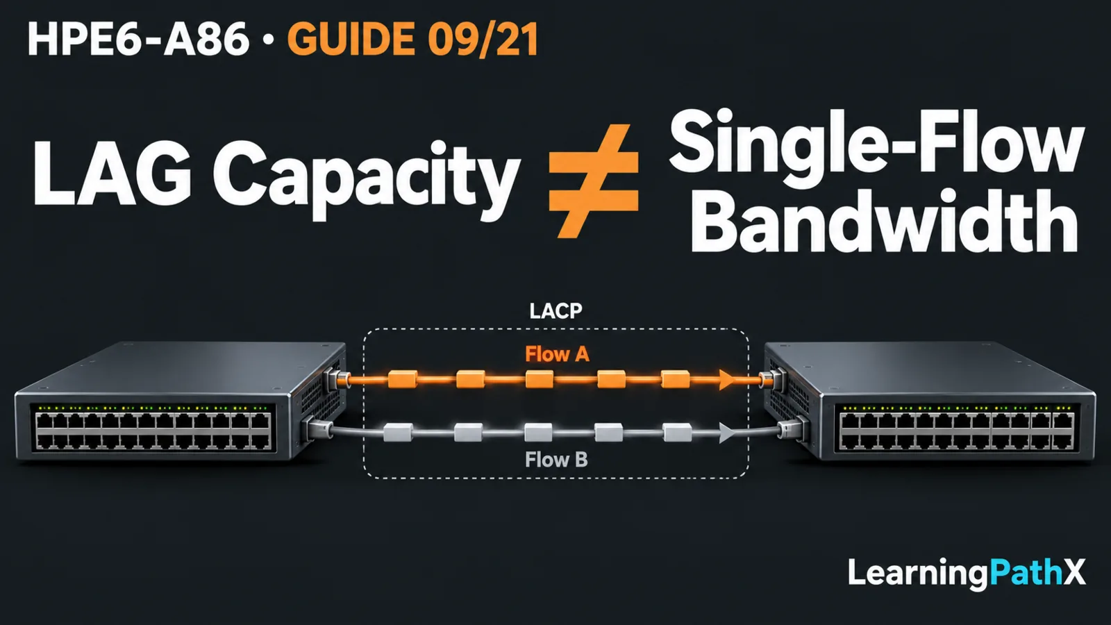
Build a Link Aggregation Control Protocol (LACP) aggregation by creating a compatible logical link at both peers, assigning the intended physical members, matching Layer 2 membership and enabling negotiation with at least one active peer. Validate the negotiated member states and actual traffic before testing one member's failure. A link aggregation group (LAG) distributes traffic across eligible members, but one flow does not automatically receive their combined bandwidth.
This procedure uses two standalone CX 6300 switches running AOS-CX 10.13 in an isolated lab. It demonstrates dynamic LACP with switch A active and switch B passive, a single access virtual local area network (VLAN) and a bounded failure/recovery test. It does not configure a multi-chassis aggregation or provision a stack. Commands are documented examples with original values, not observed successful output.
Architecture Overview: One Logical Peer at Each End
Use two compatible, reserved ports on each device: example ports 1/1/47 and 1/1/48 connect to the corresponding ports on the other switch. Confirm that the actual models provide eligible interfaces and supported media. All members must operate at the same speed; use the platform guide to check other eligibility restrictions rather than assuming that any two available ports can be bundled.
Both links in this example terminate on the same standalone switch at each end. Connecting one member to B and the other to an unrelated standalone switch C does not create the single logical partner required by this design. Supported multi-device architectures require their own documented design and are outside this procedure.
Connect one untagged test host to port 1/1/1 on each switch. Use VLAN 10, with illustrative host addresses 192.0.2.10/24 and 192.0.2.11/24. No gateway or routing is needed for the same-subnet test. There must be no additional inter-switch path.
Core Components and Negotiation
The logical LAG carries the common forwarding configuration; physical members supply its links. Configure access VLAN 10 on the logical interface consistently at both peers, rather than treating each member as an independent access path. A multi-VLAN trunk would require its own matched native/allowed design on the logical interface, not a collection of contradictory member settings.
An active LACP peer initiates negotiation. A passive peer responds to an active partner, while passive/passive does not establish the dynamic link. Active/active is also valid. Creating a LAG without enabling LACP leaves static aggregation, which is not equivalent to successful negotiation.
LACP exchanges partner and operational information; it does not prove that the VLAN configuration or endpoint addressing is correct. Distinguish a configured member from one actually selected, synchronized and forwarding.
Configure the Isolated Pair Safely
Preserve Recovery and Keep Links Inactive
Use console access, exclusive lab ownership, an unused LAG ID and ports with no conflicting configuration. Disconnect the two inter-switch cables before changes. Record the baseline and create a checkpoint on each device from Manager context:
switch# copy running-config checkpoint pre-lag09
switch# show checkpoint pre-lag09
Confirm that the checkpoint is usable before proceeding. Aggregation changes can create loops or interrupt traffic if links forward independently during preparation. This lab must remain disconnected from production; a checkpoint does not replace that boundary.
Prepare Switch A
Prompts identify the documented configuration contexts:
switch# config
switch(config)# interface 1/1/47
switch(config-if)# shutdown
switch(config-if)# exit
switch(config)# interface 1/1/48
switch(config-if)# shutdown
switch(config-if)# exit
switch(config)# vlan 10
switch(config-vlan-10)# exit
switch(config)# interface lag 1
switch(config-lag-if)# no routing
switch(config-lag-if)# vlan access 10
switch(config-lag-if)# lacp mode active
switch(config-lag-if)# no shutdown
switch(config-lag-if)# exit
switch(config)# interface 1/1/47
switch(config-if)# lag 1
switch(config-if)# shutdown
switch(config-if)# exit
switch(config)# interface 1/1/48
switch(config-if)# lag 1
switch(config-if)# shutdown
switch(config-if)# exit
switch(config)# interface 1/1/1
switch(config-if)# no routing
switch(config-if)# vlan access 10
switch(config-if)# no shutdown
switch(config-if)# end
Prepare B with the same port mapping and Layer 2 configuration, substituting lacp mode passive for the active command. Membership assignment removes nondefault member configuration, so reassert shutdown after each assignment rather than assuming an earlier administrative state survives. While the cables remain disconnected, inspect both running configurations and verify that both prepared physical members are shut down before cabling.
After both peers are prepared and cabled, enable the two physical members on each:
switch# config
switch(config)# interface 1/1/47
switch(config-if)# no shutdown
switch(config-if)# exit
switch(config)# interface 1/1/48
switch(config-if)# no shutdown
switch(config-if)# end
Validate Negotiation, Membership and Traffic
Collect these observations on both switches from Manager context:
switch# show lacp aggregates lag1
switch# show lacp interfaces 1/1/47
switch# show lacp interfaces 1/1/48
switch# show running-config
switch# show mac-address-table dynamic vlan 10
Confirm the intended aggregate, modes, members and partner identity. Read the state legend: InSync, Collecting and Distributing provide more useful evidence than a member name alone. Both links should identify the expected partner system and participate in the same intended aggregate. Out-of-sync, individual or default-neighbor states require investigation before proceeding.
Confirm the logical VLAN membership at both ends, then generate permitted host-to-host traffic. Examine learned Media Access Control (MAC) entries in VLAN 10: local host learning should point toward its access port and remote learning toward the aggregation. These are acceptance expectations, not claimed measurements. Host firewalls and endpoint state still affect application tests.
Interpret Bandwidth and Test One Failure
Hashing selects a member using the configured traffic fields. Multiple flows may distribute across members, but a single flow is not a test of their summed capacity, and distribution need not be equal. Inspect the applied hash and per-member traffic when evaluating a result rather than promising a universal multiplier.
Only after two-member acceptance, run a permitted low-rate continuous test between the lab hosts. From A's console, administratively disable one reserved member:
switch# config
switch(config)# interface 1/1/47
switch(config-if)# shutdown
switch(config-if)# end
Repeat the aggregation and member observations at both ends. Verify that the failed member leaves forwarding and the surviving member remains eligible; observe whether traffic recovers through that member. Record any interruption without inventing a convergence time or promising zero loss. Remaining capacity is lower, so this is a resilience check rather than a throughput guarantee.
Restore that physical interface with no shutdown in its interface context. Recheck synchronization, collecting/distributing state and host traffic after it rejoins. Stop if the surviving member fails or partner information differs from the intended topology; do not disable the second link merely to continue the exercise.
Rollback and Conclusion
For failure recovery or cleanup, disconnect both inter-switch cables first. Through each console, restore that device's own baseline with checkpoint rollback pre-lag09, then verify original port and management state. Rollback replaces running configuration and can remove all intervening changes, so retain exclusive ownership. Leave startup configuration unchanged during this temporary exercise.
A defensible LACP result combines compatible peers, negotiated forwarding members, consistent VLAN membership and actual traffic evidence. Failure/recovery testing checks resilience; the hash and offered flows explain bandwidth behavior. Neither a configured LAG nor two lit links proves the whole design.
Authoritative Sources
- AOS-CX 10.13 Link Aggregation Guide
- AOS-CX 10.13 Layer-2 Bridging Guide
- AOS-CX 10.13 Fundamentals Guide
- HPE Network Switching Associate Exam